![[Compaq]](../../images/compaq.gif)
![[Go to the documentation home page]](../../images/buttons/bn_site_home.gif)
![[How to order documentation]](../../images/buttons/bn_order_docs.gif)
![[Help on this site]](../../images/buttons/bn_site_help.gif)
![[How to contact us]](../../images/buttons/bn_comments.gif)
![[OpenVMS documentation]](../../images/ovmsdoc_sec_head.gif)
| Document revision date: 19 July 1999 | |
|
|
|
|
|
|
| Previous | Contents | Index |
Masked operations are enabled by the use of cntrl<15:14> of the vector control word operand. Cntrl<15> is the Masked Operation Enable (MOE) bit, and cntrl<14> is the Match True/False (MTF) bit. When cntrl<MOE> is set, masked operations are enabled. Only elements for which the corresponding Vector Mask Register (VMR) bit matches cntrl<MTF> are operated upon. If cntrl<MOE> is clear, all elements are operated upon. In either case, the Vector Length Register (VLR) limits the highest element operated upon.
Cntrl<MOE> should be zero for VMERGE and IOTA instructions;
otherwise the results are UNPREDICTABLE. Both the Vector Mask Register
(VMR) and the Match True/False bit (cntrl<MTF>) are always used
by these instructions. VMERGE and IOTA operate upon vector register
elements up to the value specified in VLR.
1.3.2 Exception Enable Bit
The vector processor does not use the IV and FU bits in the processor
status longword (PSL) to enable integer overflow and floating underflow
exception conditions. These exception conditions are enabled or
disabled on a per instruction basis for vector integer and
floating-point instructions by bit <13> in the vector control
word operand (cntrl<EXC>). When cntrl<EXC> is set, floating
underflow is enabled for vector floating-point instructions, and
integer overflow is enabled for vector integer instructions. When
cntrl<EXC> is clear, floating underflow and integer overflow are
disabled. Note that for VLD/VGATH instructions bit<13> is used
and labeled differently.
1.3.3 Modify Intent Bit
The Modify Intent (MI) bit is used by the software to indicate to the vector processor that a majority of the memory locations being loaded by VLD/VGATH instructions will later be stored into, and so become modified, by VST/VSCAT instructions. When informed of software's intent to modify, some vector processor implementations can optimize the vector loads and stores performed on these locations.
The MI bit resides in bit<13> of the vector control word operand (cntrl<MI>) and is used only in VLD and VGATH instructions. A vector processor implementation is not required to implement cntrl<MI>.
For vector processors that implement cntrl<MI>, software uses the bit in a VLD or VGATH instruction in the following way:
Vector processors that do not implement cntrl<MI> ignore the setting of this bit in the control word for VLD and VGATH.
The results of VLD/VGATH and VST/VSCAT are unaffected by the setting of
cntrl<MI>. This includes memory management, where access-checking
is done with read intent for VLD/VGATH even if cntrl<MI> is set.
However, incorrectly setting cntrl<MI> can prevent the
optimization of these instructions.
1.3.4 Register Specifier Fields
The Va (cntrl<11:8>), Vb (cntrl<7:4>), and Vc
(cntrl<3:0>) fields of the vector control word operand are
generally used to select vector registers. Some vector instructions use
these fields to encode other instruction-specific information as shown
later in this section.
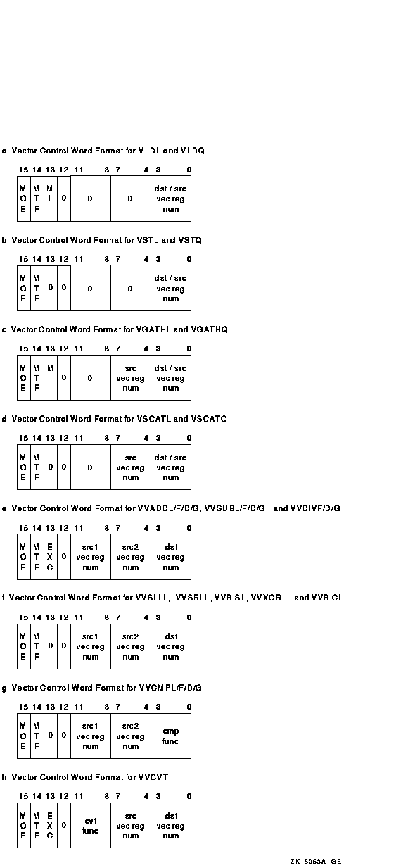
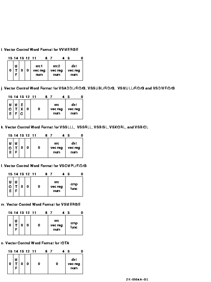
1.3.5 Vector Control Word Formats
Depending on the instruction, the vector control word can specify up to two vector registers as sources, and one vector register as a destination. Other information may be encoded in the vector control word, as shown in Figure 1-11a to Figure 1-11n. Bits that are shown as "0" should be zero (SBZ). Execution of vector instructions with illegal, inconsistent, or unspecified control word fields produces UNPREDICTABLE results.
Figure 1-11a depicts the vector control word for VLDL and VLDQ.
Figure 1-11b depicts the vector control word for VSTL and VSTQ.
Figure 1-11c depicts the vector control word for VGATHL and VGATHQ.
Figure 1-11d depicts the vector control word for VSCATL and VSCATQ.
Figure 1-11e depicts the vector control word for VVADDL/F/D/G, VVSUBL/F/D/G, VVMULL/F/D/G, and VVDIVF/D/G.
Figure 1-11f depicts the vector control word for VVSLLL, VVSRLL, VVBISL, VVXORL, and VVBICL. Cntrl<EXC> should always be zero for these instructions, otherwise the results are UNPREDICTABLE.
Figure 1-11g depicts the vector control word for VVCMPL/F/D/G. The Vc field (cntrl<3:0>) is used to specify the compare function.
Figure 1-11h depicts the vector control word for VVCVT. The Va field (cntrl <11:8>) is used to specify the convert function.
Figure 1-11i depicts the vector control word for VVMERGE.
Figure 1-11j depicts the vector control word for VSADDL/F/D/G, VSSUBL/F/D/G, VSMULL/F/D/G, and VSDIVF/D/G.
Figure 1-11k depicts the vector control word for VSSLLL, VSSRLL, VSBISL, VSXORL, and VSBICL. Cntrl<EXC> should be zero for these instructions; otherwise, the results are UNPREDICTABLE.
Figure 1-11l depicts the vector control word for VSCMPL/F/D/G. The Vc field (cntrl<3:0>) is used to specify the compare function.
Figure 1-11m depicts the vector control word for VSMERGE.
Figure 1-11n depicts the vector control word for IOTA.
Figure 1-11 Vector Control Word Format
Certain restrictions are placed on the addressing mode combinations usable within a single vector instruction. These combinations involve the logically inconsistent simultaneous use of a value as both a source operand (that is, a .rw, .rl, or .rq operand) and an address. Specifically, if within the same instruction the contents of register Rn is used as both a part of a source operand and as an address in an addressing mode that modifies Rn (that is, autodecrement, autoincrement, or autoincrement deferred), the value of the scalar source operand is UNPREDICTABLE.
Use of short literal mode for the scalar source operand of a vector floating-point instruction causes UNPREDICTABLE results.
If a Store Vector Register Data into Memory (VST) or Scatter Memory Data into Vector Register (VSCAT) instruction overwrites anything needed for calculation of the memory addresses to be written, the result of the VST or VSCAT is UNPREDICTABLE.
If the same vector register is used as both source and destination in a Gather Memory Data into Vector Register (VGATH) instruction, the result of the VGATH is UNPREDICTABLE.
When the addressing mode of the BASE operand used in a VLD, VST, VGATH,
or VSCAT instruction is immediate, the results of the instruction are
UNPREDICTABLE.
1.3.7 VAX Condition Codes
The vector instructions do not affect the condition codes in the
processor status longword (PSL) of the associated scalar processor.
1.3.8 Illegal Vector Opcodes
An illegal vector opcode is defined as a vector opcode to which no vector processor function is currently assigned. Opcodes that are not identified in <REFERENCE>(mnemonics) as vector opcodes are neither decoded nor executed by the vector processor.
An implementation is permitted to report an illegal vector opcode in one of the following ways:
The way in which a particular illegal vector opcode is reported is
implementation specific.
1.4 Assembler Notation
The assembler notation uses a format that is different from the operand specifiers for the vector instructions. The number and order of operands is not the same as the instruction-stream format. For example, vector-to-vector addition is denoted by the assembler as "VVADDL V1, V2, V3" instead of "VVADDL X123". The assembler always generates immediate addressing mode (I#constant) for vector control word operands. The assembler notation for vector instructions uses opcode qualifiers to select whether vector processor exception conditions are enabled or disabled, and to select the value of cntrl<MTF> in masked, VMERGE, and IOTA operations. The appropriate opcode is followed by a slash (/). The following qualifiers are supported:
The following examples use several of these qualifiers:
VVADDF/1   V0, V1, V2   ;Operates on elements with mask bit set
VVMULD/0   V0, V1, V2   ;Operates on elements with mask bit clear
VVADDL/V   V0, V1, V2   ;Enables exception conditions
                         (integer overflow here)
VVSUBG/U0  V0, V1, V2   ;Enables floating underflow and
                        ;Operates on elements with mask bit clear
|
VLDL/M base,#4,V1 ;Indicates Modify Intent |
1.5 Execution Model
A typical processor consists of a VAX scalar processor and its
associated vector processor, which contains vector registers and vector
function units. The scalar and vector processors may execute
asynchronously. The VAX scalar processor decodes both scalar and vector
instructions following the operand specifier evaluation rules stated in
the VAX Architecture Reference Manual, but executes only the scalar instructions. The scalar
processor passes the information required to execute a vector
instruction to the vector processor. This information may include the
vector opcode, scalar source operands, and vector control words. The
vector processor performs the required operation, such as loading data
from memory, storing data to memory, or manipulating data already
loaded into its vector registers.
The scalar processor may decode a vector instruction before checking whether the vector processor should receive it. Exceptions on vector instruction operands may occur during this decoding and may be taken before the attempt to send the decoded instruction to the vector processor. The scalar processor performs one of the following operations when sending a decoded vector instruction to the vector processor. Recall that because the vector and scalar processors can execute asynchronously, a VPSR state transition may not be seen immediately by the scalar processor.
The following flow details how vector instruction decode proceeds from the scalar processor:
DO WHILE (the scalar processor has a decoded vector instruction for
          the vector processor)
  IF (the vector processor is viewed as disabled -- the scalar processor
     sees VPSR<VEN> as clear) THEN

     enter the vector processor disabled fault handler.
  ELSE
     IF (asynchronous memory management handling is implemented
        AND VPSR<PMF> is set) THEN
        enter the memory management exception handler.
        {The vector processor clears VPSR<PMF>.}
     ELSE

        BEGIN
          {If asynchronous memory management handling is
          implemented and VPSR<MF> is set, the vector processor
          clears VPSR<MF>, and retries the faulting memory
          reference before any new vector instructions in the
          queue are executed.}
          IF (the vector processor instruction queue is not full) THEN
             BEGIN
               Send the decoded instruction to the vector processor
               for execution.
               IF (the decoded instruction is a vector memory access
                   instruction AND synchronous memory management
                   handling is implemented) THEN
                  ensure instruction completion without the occurrence
                  of memory management exceptions.
             END
        END
END
|
If asynchronous memory management handling is implemented, and VPSR<MF> is set when the scalar processor sends the vector processor an instruction, the vector processor clears VPSR<MF>, and retries the faulting memory reference before any new vector instructions in the queue are executed.
The VAX scalar processor need not wait for the vector processor to complete its operation before processing other instructions. Thus, the scalar processor could be processing other VAX instructions while the vector processor is performing vector operations. However, if the scalar processor issues an MFVP instruction to the vector processor, the scalar processor must wait for the MFVP result to be written before processing other instructions.
Because the scalar and vector processors may execute asynchronously, it is possible to context switch the scalar processor before the vector processor is idle. Software is responsible for ensuring that scalar and vector memory management remains synchronized, and that all exceptions get reported in the context of the process where they occurred. This is achieved by making sure all vector memory accesses complete, and then disabling the vector processor before any scalar context switch.
The vector processor may have its own translation buffer (TB) and cache
and may have separate paths to memory, or it may share these resources
with the scalar processor.
1.5.1 Access Mode Restrictions
In general, processes are expected to use the vector processor in only one mode. However, multimode use of the vector processor by a process is allowed. Software decides whether to allow vector processor exceptions from vector instructions executed in a previous access mode to be reported in the current mode. The preferred method is to report all vector processor exceptions in the access mode where they occurred. This is achieved by requiring a process that uses the vector processor to execute a SYNC instruction before changing to an access mode where additional vector instructions are executed.
For correct access checking of vector memory references, the vector
processor must know the access mode in effect when a vector memory
access instruction is issued by the scalar processor.
1.5.2 Scalar Context Switching
With the addition of a vector processor, the required steps in performing a scalar context switch change. The following procedure outlines the required method software should use for scalar context switching:
Although not required by the architecture, software may wait for VPSR<BSY> to be clear after disabling the vector processor when performing a scalar context switch, which provides the following advantages:
If software does not wait for VPSR<BSY> to be clear, it is possible that while a normal scalar context switch to a new process is being performed, the vector processor may still be executing non-memory-access instructions from the previous process.
The required steps for Vector Context Switching are discussed in
Section 1.6.4, Handling Disabled Faults and Vector Context Switching.
1.5.3 Overlapped Instruction Execution
To improve performance, the vector processor may overlap the execution of multiple instructions---that is, execute them concurrently. Further, when no data dependencies are present, the vector processor may complete instructions out of order relative to the order in which they were issued. A vector processor implementation can perform overlapped instruction execution by having separate function units for such operations as addition, multiplication, and memory access. Both data-dependent and data-independent instructions can be overlapped; the former by a technique known as chaining, which is described in the next section. In many instances, overlapping allows an operation from one instruction to be performed in any order with respect to an operation of another instruction.
When vector arithmetic exceptions occur during overlapped instruction execution, exception handling software may not see the same instruction state and exception information that would be returned from strictly sequential execution. Most notably, the VAER could indicate the exception conditions and destination registers of a number of vector instructions that were executing concurrently and encountered exceptions. Exception reporting during chained execution is discussed further in Section 1.5.3.1.
To ensure correct program results and exception reporting, the architecture does place requirements on the ordering among the operations of one vector instruction and those of another. The primary goal of these requirements is to ensure that the results obtained from both the overlapped and strictly sequential execution of data-dependent instructions are identical. A secondary goal is to establish places within the instruction stream where software is guaranteed to receive the reporting of exceptions from a chain of data-dependent instructions.
In many cases, these requirements ensure the obvious: for example, an output vector register element of one arithmetic instruction must be computed before it can be used as an input element to a subsequent instruction. But, a number of the things ensured are not obvious: for example, a Memory Instruction Synchronization (MSYNC) instruction must report exceptions encountered in generating a value of Vector Mask Register (VMR) that is used in a previously issued masked store instruction.
To precisely define the requirements on the ordering among operations,
Section 1.5.3.3 discusses the "dependence" among their results
(the vector register elements and control register bits produced by the
operations).
1.5.3.1 Vector Chaining
The architecture allows vector chaining, where the results of one vector instruction are forwarded (chained) to another before the input vector of the first instruction has been completely processed. In this way, the execution of data-dependent vector instructions may be overlapped. Thus, chaining is an implementation-dependent feature that is used to improve performance.
With some restrictions stated below, the vector processor may chain a number of instructions. Usually, each instruction is performed by a separate function unit. The number and types of instructions allowed within a chained sequence (often referred to as a "chain") are implementation dependent. Typically, implementations will attempt to chain sequences of two or three instructions such as: operate-operate, operate-store, load-operate, operate-operate-store, and load-operate-store. Load-operate-operate-store may also be possible.
The following is an example of a sequence that an implementation will often chain:
VVADDF V0, V1, V2 VVMULF V2, V3, V4 |
The destination of the VVADDF is a source of the succeeding VVMULF. The VVMULF begins executing when the first sum element of the VVADDF is available.
A number of instructions within a chained sequence can encounter exceptions. For each instruction that encounters an exception, the vector processor records the exception condition type and destination register number in the Vector Arithmetic Exception Register (VAER). When the last instruction within the chain completes, the VAER will show the exception condition type and destination register number of all instructions that encountered exceptions within the chain. Furthermore, when the vector processor disabled fault is finally generated for the exceptions, the VAER may also indicate exception state for instructions issued after the last instruction within the chain. This effect is possible due to the asynchronous exception-reporting nature of the vector processor.
Furthermore, for each instruction that encounters an exception within a chain, the default result, as defined in Section 1.6.2, is forwarded as the source operand to the next instruction. This has the effect that default results and exceptions can propagate down through a chain. Note that the default result of one instruction may be overwritten by another instruction before the exception is taken.
Consider the following:
VVADDG V1, V2, V3 ;gets Floating Overflow VVGEQG V3, V4 ;gets Floating Reserved Operand VVMULG V4, V5, V3 ;overwrites V3 |
For the previous example, assume that an exception is taken after the completion of the VVMULG. The VAER will indicate: Floating Overflow and Floating Reserved Operand exception condition types; and V3 as a destination register. However, no default result will be found in the appropriate element of V3 because it has been overwritten by the VVMULG.
The architecture allows a vector load to be chained into a vector operate instruction provided the operate instruction can be suspended and resumed to produce the correct result if the vector load gets a memory management exception. Consider this example:
VLDL A, #4, V0 VVADDF V0, V1, V1 |
In synchronous memory management mode, the VVADDF cannot be chained into the VLDL until the VLDL is ensured to complete without a memory management exception. This occurs because the scalar processor is not even allowed to issue the VVADDF to the vector processor until the memory management checks for the VLDL have been completed. In asynchronous memory management mode, the VVADDF may be chained into the VLDL prior to the completion of memory management exception checking. This is possible because a memory management exception in asynchronous memory management mode provides sufficient state to restart both the VLDL and the VVADDF when the memory management exception is corrected.
The architecture allows a vector operate instruction to be chained into a store instruction. If the vector operate instruction encounters an arithmetic exception, the exception condition type and destination register number are recorded in the Vector Arithmetic Exception Register (VAER). The default result generated by that instruction (in some cases an encoded reserved operand) may be written to memory by the store instruction before the exception is reported.
| Previous | Next | Contents | Index |
|
|
| privacy and legal statement | ||
| 4515CH10_001.HTML | ||