![[Compaq]](../../images/compaq.gif)
![[Go to the documentation home page]](../../images/buttons/bn_site_home.gif)
![[How to order documentation]](../../images/buttons/bn_order_docs.gif)
![[Help on this site]](../../images/buttons/bn_site_help.gif)
![[How to contact us]](../../images/buttons/bn_comments.gif)
![[OpenVMS documentation]](../../images/ovmsdoc_sec_head.gif)
| Document revision date: 19 July 1999 | |
|
|
|
|
|
|
| Previous | Contents | Index |
At this time, the only devices approved for use on multihost SCSI OpenVMS Cluster systems are those listed in Table A-2. While not specifically approved for use, other disk devices might be used in a multihost OpenVMS Cluster system when they conform to the following requirements:
Finally, if the device or any other device on the same segment will be
hot plugged, then the device must meet the electrical requirements
described in Section A.7.6.2.
A.7.8 Grounding Requirements
This section describes the grounding requirements for electrical systems in a SCSI OpenVMS Cluster system.
Improper grounding can result in voltage differentials, called ground offset voltages, between the enclosures in the configuration. Even small ground offset voltages across the SCSI interconnect (as shown in step 3 of Table A-8) can disrupt the configuration and cause system performance degradation or data corruption.
Table A-8 describes important considerations to ensure proper grounding.
| Step | Description |
|---|---|
| 1 | Ensure that site power distribution meets all local electrical codes. |
| 2 |
Inspect the entire site power distribution system to ensure that:
|
| 3 |
If you have difficulty verifying these conditions, you can use a
hand-held multimeter to measure the ground offset voltage between any
two cabinets. To measure the voltage, connect the multimeter leads to
unpainted metal on each enclosure. Then determine whether the voltage
exceeds the following allowable ground offset limits:
The multimeter method provides data for only the moment it is measured. The ground offset values may change over time as additional devices are activated or plugged into the same power source. To ensure that the ground offsets remain within acceptable limits over time, Compaq recommends that you have a power survey performed by a qualified electrician. |
| 4 | If you are uncertain about the grounding situation or if the measured offset exceeds the allowed limit, Compaq recommends that a qualified electrician correct the problem. It may be necessary to install grounding cables between enclosures to reduce the measured offset. |
| 5 | If an unacceptable offset voltage was measured and a ground cable was installed, then measure the voltage again to ensure it is less than the allowed limits. If not, an electrician must determine the source of the ground offset voltage and reduce or eliminate it. |
This appendix contains information about MEMORY CHANNEL, a high-performance cluster interconnect technology. MEMORY CHANNEL, which was introduced in OpenVMS Alpha Version 7.1, supports several configurations.
This chapter contains the following sections:
| Section | Content |
|---|---|
| Product Overview | High-level introduction to the MEMORY CHANNEL product and its benefits, hardware components, and configurations. |
| Technical Overview | More in-depth technical information about how MEMORY CHANNEL works. |
MEMORY CHANNEL is a high-performance cluster interconnect technology for PCI-based Alpha systems. With the benefits of very low latency, high bandwidth, and direct memory access, MEMORY CHANNEL complements and extends the unique ability of an OpenVMS Cluster to work as a single, virtual system.
MEMORY CHANNEL offloads internode cluster traffic (such as lock management communication) from existing interconnects---CI, DSSI, FDDI, and Ethernet---so that they can process storage and network traffic more effectively. MEMORY CHANNEL significantly increases throughput and decreases the latency associated with traditional I/O processing.
Any application that must move large amounts of data among nodes will
benefit from MEMORY CHANNEL. It is an optimal solution for applications
that need to pass data quickly, such as real-time and transaction
processing. MEMORY CHANNEL also improves throughput in high-performance
databases and other applications that generate heavy OpenVMS Lock
Manager traffic.
B.1.1 MEMORY CHANNEL Features
MEMORY CHANNEL technology provides the following features:
When first introduced in OpenVMS Version 7.1, MEMORY CHANNEL supported a maximum of four nodes in a 10-foot radial topology. Communication occurred between one sender-receiver pair at a time. MEMORY CHANNEL Version 1.5 introduced support for eight nodes, a new adapter (CCMAA--BA), time stamps on all messages, and more robust performance.
MEMORY CHANNEL Version 2.0 provides the following new capabilities:
A MEMORY CHANNEL cluster is joined together by a hub, a desktop-PC sized unit which provides a connection among systems. The hub is connected to a system's PCI adapter by a link cable. Figure B-1 shows all three hardware components required by a node to support MEMORY CHANNEL:
Figure B-1 MEMORY CHANNEL Hardware Components

The PCI adapter pictured in Figure B-1 has memory mapping logic that enables each system to communicate with the others in the MEMORY CHANNEL cluster.
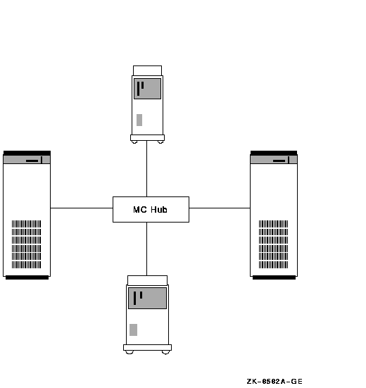
Figure B-2 shows an example of a four-node MEMORY CHANNEL cluster with a hub at its center.
Figure B-2 Four-Node MEMORY CHANNEL Cluster
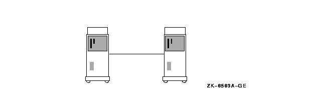
A MEMORY CHANNEL hub is not required in clusters that contain only two nodes. In a two-node configuration like the one shown Figure B-3, the same adapters and cable are used, and one of the PCI adapters serves as a virtual hub. You can continue to use the adapters and cable if you expand to a larger configuration later.
Figure B-3 Virtual Hub MEMORY CHANNEL Cluster
MEMORY CHANNEL requires a central hub in configurations of three or more nodes. The MEMORY CHANNEL hub contains active, powered electronic components. In the event of a hub failure, resulting from either a power shutdown or component failure, the MEMORY CHANNEL interconnect ceases operation. This type of failure does not occur with the other cluster interconnects, such as CI, DSSI, and most LAN configurations.
Compaq therefore recommends that customers with MEMORY CHANNEL configurations who have high availability requirements consider using one of the following configurations to provide a second backup interconnect:
The use of MEMORY CHANNEL imposes certain requirements on memory and on
your choice of diagnostic tools.
B.1.5.1 Memory Requirements
MEMORY CHANNEL consumes memory during normal operations. Each system in
your MEMORY CHANNEL cluster must have at least 128 MB of memory.
B.1.5.2 Large-Memory Systems' Use of NPAGEVIR Parameter
On systems containing very large amounts of nonpaged pool memory, MEMORY CHANNEL may be unable to complete initialization. If this happens, the console displays the following message repeatedly:
Hub timeout - reinitializing adapter |
To fix this problem, examine the value of the SYSGEN parameter
NPAGEVIR. If its value is greater than 1 gigabyte, consider lowering it
to about half of that. Thereafter, a reboot of your system should allow
the MEMORY CHANNEL to complete initialization.
B.1.6 Configurations
Figure B-4 shows a basic MEMORY CHANNEL cluster that uses the SCSI interconnect for storage. This configuration provides two advantages: high performance on the MEMORY CHANNEL interconnect and low cost on the SCSI interconnect.
Figure B-4 MEMORY CHANNEL- and SCSI-Based Cluster
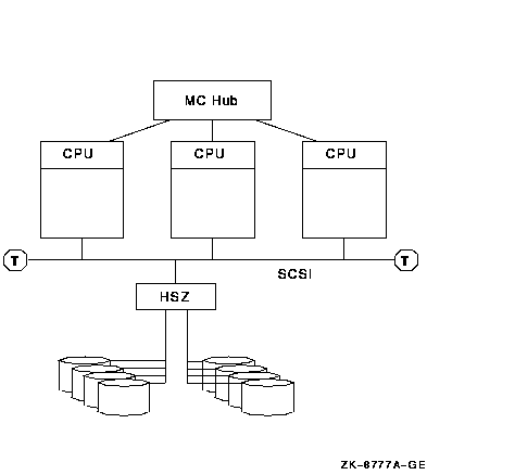
In a configuration like the one shown in Figure B-4, the MEMORY CHANNEL interconnect handles internode communication while the SCSI bus handles storage communication.
You can integrate MEMORY CHANNEL with your current systems. Figure B-5 shows an example of how to add MEMORY CHANNEL to a mixed-architecture CI- and SCSI-based cluster. In this example, the BI- and XMI-based VAX systems are joined in the same CI cluster with the PCI-based Alpha MEMORY CHANNEL systems.
Figure B-5 MEMORY CHANNEL CI- and SCSI-Based Cluster
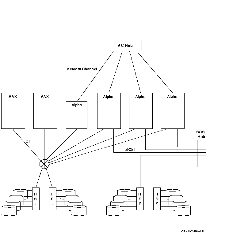
Because the MEMORY CHANNEL interconnect is not used for storage and booting, you must provide access to a boot device through one of the other interconnects. To use Figure B-5 as an example, one of the CI-based disks would be a good choice for a boot device because all nodes have direct access to it over the CI.
MEMORY CHANNEL can also be integrated into an existing DSSI cluster, as shown in Figure B-6.
Figure B-6 MEMORY CHANNEL DSSI-Based Cluster
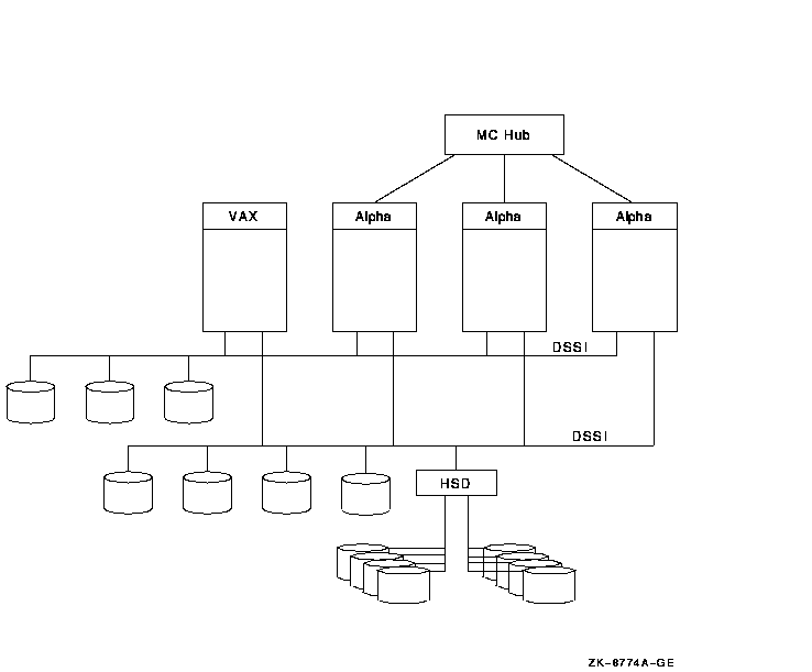
As Figure B-6 shows, the three MEMORY CHANNEL systems and the VAX
system have access to the storage that is directly connected to the
DSSI interconnect as well as to the SCSI storage attached to the HSD
controller. In this configuration, MEMORY CHANNEL handles the Alpha
internode traffic, while the DSSI handles the storage traffic.
B.1.6.1 Configuration Support
MEMORY CHANNEL supports the platforms and configurations shown in Table B-1.
| Requirement | Description |
|---|---|
| Configuration |
MEMORY CHANNEL supports the following configurations:
|
| Cables |
MEMORY CHANNEL supports the following cables:
|
| Host systems |
MEMORY CHANNEL supports the following systems:
|
You can configure a computer in an OpenVMS Cluster system with both a MEMORY CHANNEL Version 1.5 hub and a MEMORY CHANNEL Version 2.0 hub. However, the version number of the adapter and the cables must match the hub's version number for MEMORY CHANNEL to function properly. In other words, you must use MEMORY CHANNEL Version 1.5 adapters with the MEMORY CHANNEL Version 1.5 hub and MEMORY CHANNEL Version 1.5 cables. Similarly, you must use MEMORY CHANNEL Version 2.0 adapters with the MEMORY CHANNEL Version 2.0 hub and MEMORY CHANNEL Version 2.0 cables. |
This section describes in more technical detail how MEMORY CHANNEL
works.
B.2.1 Comparison With Traditional Networks and SMP
You can think of MEMORY CHANNEL as a form of "stretched SMP bus" that supports enough physical distance to interconnect up to eight systems. However, MEMORY CHANNEL differs from an SMP environment where multiple CPUs can directly access the same physical memory. MEMORY CHANNEL requires each node to maintain its own physical memory, even though the nodes share MEMORY CHANNEL global address space.
MEMORY CHANNEL fills a price/performance gap between the high performance of SMP systems and traditional packet-based networks. Table B-2 shows a comparison among the characteristics of SMP, MEMORY CHANNEL, and standard networks.
| Characteristics | SMP | MEMORY CHANNEL | Standard Networking |
|---|---|---|---|
| Bandwidth (MB/s) | 1000+ | 100+ | 10+ |
| Latency (ms/simplest message) | 0.5 | Less than 5 | About 300 |
| Overhead (ms/simplest message) | 0.5 | Less than 5 | About 250 |
| Hardware communication model | Shared memory | Memory-mapped | Message passing |
| Hardware communication primitive | Store to memory | Store to memory | Network packet |
| Hardware support for broadcast | n/a | Yes | Sometimes |
| Hardware support for synchronizaton | Yes | Yes | No |
| Hardware support for node hot swap | No | Yes | Yes |
| Software communication model | Shared memory | Fast messages, shared memory | Messages |
| Communication model for errors | Not recoverable | Recoverable | Recoverable |
| Supports direct user mode communication | Yes | Yes | No |
| Typical physical interconnect technology | Backplane etch | Parallel copper cables | Serial fiber optics |
| Physical interconnect error rate |
Extremely low
order: less than one per year |
Extremely low
order: less than one per year |
Low order:
several per day |
| Hardware interconnect method | Special purpose connector and logic | Standard I/O bus adapter (PCI) | Standard I/O bus adapter (PCI and others) |
| Distance between nodes (m) | 0.3 | 20 (copper) or 60 (fiber-optic) in a hub configuration and 10 (copper) or 30 (fiber-optic) in a two-node configuration | 50--1000 |
| Number of nodes | 1 | 8 | Hundreds |
| Number of processors | 6--12 | 8 times the maximum number of CPUs in an SMP system | Thousands |
| Failure model | Fail together | Fail separately | Fail separately |
B.2.2 MEMORY CHANNEL in the OpenVMS Cluster Architecture
As Figure B-7 shows, MEMORY CHANNEL functionality has been
implemented in the OpenVMS Cluster architecture just below the System
Communication Services layer. This design ensures that no changes are
required to existing applications because higher layers of OpenVMS
Cluster software are unchanged.
Figure B-7 OpenVMS Cluster Architecture and MEMORY CHANNEL
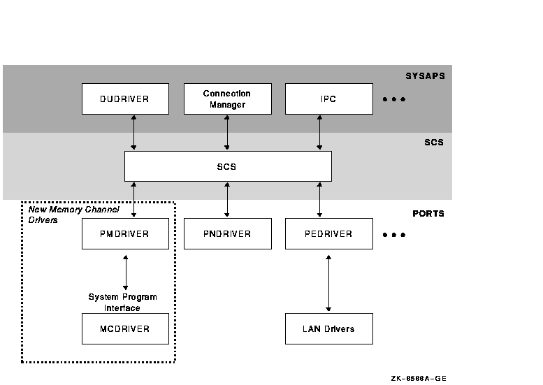
MEMORY CHANNEL software consists of two new drivers:
| Driver | Description |
|---|---|
| PMDRIVER | Emulates a cluster port driver. |
| MCDRIVER | Provides MEMORY CHANNEL services and an interface to MEMORY CHANNEL hardware. |
| Previous | Next | Contents | Index |
|
|
| privacy and legal statement | ||
| 6318PRO_022.HTML | ||